CCNA – Default Routing, RIP v2, and VMware Workstation NICs
Hi All – we are going thru the Todd Lammle CCNA Study Guide and just got virtual routing figured out from our internal lab. There will be more added to this post, so this is just a quick note.
Here’s the problem we’re solving: CORP, R1, R2, and R3 all connected as shown:
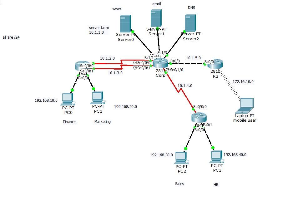
In the drawing, R3 is used to communicate with the wireless network. Within Chapter 8 of Lammle’s book, he also uses R3 to connect to another interface to provide egress from the isolated network.
So here’s what we did:
- Configure VMware Workstation networking.
- Attach router interfaces to the VMware Workstation virtual interfaces.
- Configure default routing on R3.
- Verify RIPv2 updates on other virtual routers.
All of this is done using Dynamips/Dynagen.
All of the Files!
Let’s start by jumping the gun and posting every file we need within a handy .ZIP archive. We’ll put in the .NET file and each of the running-config files from our emulated Cisco 3640 routers.
Download the configurations here! And now we can move on forward.
Configure VMware Workstation Networking
We are using VMware Workstation 9 as we got that from taking the ICM VMware VCP5 training class. So we are not using Workstation 10 but for our purposes…this is Fine.
When you first install Workstation 9 you will see that you have only a couple virtual network interfaces defined – typically VMnet0 (auto-bridging), VMnet1 (host-only), and VMnet8 (NAT). For the Lammle Lab we added 6 more virtual NICs to align with his drawing and networks:
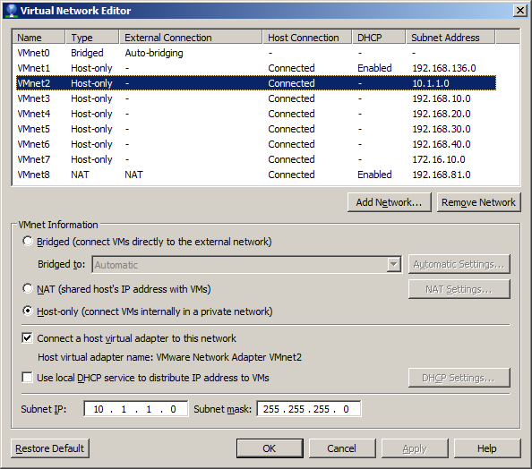
In the above drawing we see the 6 virtual interfaces where the 10.1.1.0/24 network is highlighted. Note that we disabled VMware DHCP for all of these interfaces; although we hook up clients (such as Damn Small Linux clients), we’ll use the emulated routers for DHCP as necessary.
- VMnet2 – “Core” network, 10.1.1.0/24.
- VMnet3 – “Finance” network, 192.168.10.0/24.
- VMnet4 – “Marketing” network, 192.168.20.0/24.
- VMnet5 – “Sales” network, 192.168.30.0/24.
- VMnet6 – “HR” network, 192.168.40.0/24.
- VMnet7 – “Mobile User” network, 172.16.10.0/24.
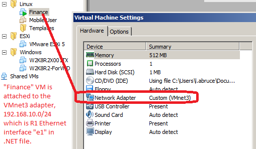
Note that all of these networks are fictional; we simply spin up different VMs within Workstation and attach them to the various VMnetX virtual interfaces to emulate different scenarios. For example, here is a “Finance” workstation attached to VMnet3:
Setup Dynamips/Dynagen .NET File
The Dynagen .NET file allows us to create an entire virtual lab of Cisco routers. There are many tutorials on creating a .NET file so let’s concentrate on how we hooked up the VMware Workstation virtual network interfaces to logical Cisco router interfaces.
First, here’s the .NET file for the R1 router (which provides DHCP address to the “Finance” VM from above):
    [[ROUTER R1]]
        model = 3640
        console = 50802
        slot0 = NM-4T
        s0/0 = CORP s0/0
        s0/1 = CORP s0/1
        slot1 = NM-4E
        # Finance - VMnet3 - 192.168.10.10/24
        e1/0 = NIO_gen_eth:\Device\NPF_{76F54328-E3F8-42BB-BACB-CA4127AAE4E4}
        # Marketing - VMnet4 - 192.168.20.10/24
        e1/1 = NIO_gen_eth:\Device\NPF_{467F256E-6417-4DD9-9A67-8A5709C0BCC6}
In the above we have two “slots” (emulated Cisco modules) attached to a virtual Cisco 3640 router. The first slot is a 4-port serial interface (NM-4T) which is attached to two corresponding virtual interfaces on the CORP router. You can see that the second slot is type NM-4E which is simply a four-port Ethernet (10Mb/sec) interface. (Slow, but that doesn’t matter for small labs.) You can also see that we have a comment indicating the mapping between an interface and VMware Workstation’s network labeling as well as the NIO_gen_eth entries. Those are provided to us by the Network device list.cmd script within the Dynamips installation folder. That command maps the available network interfaces on the PC to device names that Dynamips can load via the WinPcap interface. We end up with the following list on our machine:
C:\Users\LE34E~1.ABR\AppData\Local\Temp>"C:\Program Files (x86)\Dynamips\Network device list.cmd"

Network adapters on this machine:

NIO_gen_eth:\Device\NPF_{3BF34483-23DF-4017-8074-54241CA2F0AF}
 Name      : VMware Network Adapter VMnet8
 Desciption: VMware Virtual Ethernet Adapter
[...output cut...]

NIO_gen_eth:\Device\NPF_{8FF58C8B-E357-48AC-9454-30F57406441E}
 Name      : VMware Network Adapter VMnet7
 Desciption: VMware Virtual Ethernet Adapter

NIO_gen_eth:\Device\NPF_{29CFE61E-C5C8-4E7B-A29C-3EB85F407EC9}
 Name      : VMware Network Adapter VMnet5
 Desciption: VMware Virtual Ethernet Adapter

NIO_gen_eth:\Device\NPF_{76F54328-E3F8-42BB-BACB-CA4127AAE4E4}
 Name      : VMware Network Adapter VMnet3
 Desciption: VMware Virtual Ethernet Adapter

NIO_gen_eth:\Device\NPF_{467F256E-6417-4DD9-9A67-8A5709C0BCC6}
 Name      : VMware Network Adapter VMnet4
 Desciption: VMware Virtual Ethernet Adapter

NIO_gen_eth:\Device\NPF_{F978F712-8FAF-4A31-AC98-3F3971C652EE}
 Name      : VMware Network Adapter VMnet6
 Desciption: VMware Virtual Ethernet Adapter

NIO_gen_eth:\Device\NPF_{8021F1B0-753D-4917-A0E7-600CB90C8C5C}
 Name      : VMware Network Adapter VMnet2
 Desciption: VMware Virtual Ethernet Adapter
We highlighted the two NIO_gen_eth references we referenced for the R1 router .NET file above. For the R3 router, we added a reference to VMnet8, NM-1FE-TX 1-port Fast Ethernet (100Mb/sec) interface as such:
    [[ROUTER R3]]
        model = 3640
        console = 50804
        slot0 = NM-1FE-TX
        f0/0 = CORP f1/0
        slot1 = NM-4E
        # Mobile User - VMnet7 - 172.16.10.10/24
        e1/0 = NIO_gen_eth:\Device\NPF_{8FF58C8B-E357-48AC-9454-30F57406441E}
        slot2 = NM-1FE-TX
        # Egress - VMnet8 - 192.168.81.10/24
        f2/0 = NIO_gen_eth:\Device\NPF_{3BF34483-23DF-4017-8074-54241CA2F0AF}
So we end up with *three* slots for R3 – slot0 is a NM-1FE-TX 1-port Fast Ethernet adapter to the CORP router, slot1 is a NM-4E 4-port Ethernet adapter we’ll use to connect to emulated wireless clients, and slot2 is the connection to VMnet8 so we can egress from our isolated network to the Internet.
We won’t cover the rest of the .NET file but you can download the complete file here if it will help you in your own studies!
Setup Routing
For this section we’ll cover what we did for R1 (the “Finance” router) and for R3 (the egress router). Once we get the .NET file loaded and a console opened to both R1 and R3, we’ll take a look at just a few entries.
A Bit of Explanation…
In the discussion below, please keep in mind that routers R1 and R3 are *not* directly connected. They are connected indirectly via the CORP router…and we don’t show the CORP router configuration below. So for our purposes, just assume that R1 and R3 can communicate with each other. Our use case for this article is how R1 (and any connected VM clients) can actually egress the isolated network using RIPv2.
Also – you can download the entire set of .NET and router configuration files we used in our lab from our provided link above.
R1 Configuration Setup
Let’s start with R1, which is connected to the “Finance” network (192.168.10.0/24) on interface Ethernet1/0:
ip dhcp excluded-address 192.168.10.1 192.168.10.10
!
ip dhcp pool Finance
   network 192.168.10.0 255.255.255.0
   default-router 192.168.10.10
   dns-server 192.168.81.2
[...output cut...]
interface Serial0/0
 description 1st Connection to Corp Router
 ip address 10.1.2.2 255.255.255.0
 serial restart-delay 0
!
[...output cut...]
interface Ethernet1/0
 description Connection to Finance PC
 ip address 192.168.10.10 255.255.255.0
 half-duplex
!
[...output cut...]
router rip
 version 2
 network 10.0.0.0
 network 192.168.10.0
 network 192.168.20.0
!
In the above, we show a reference to the CORP router as R3 and R1 are *not* directly connected; see the link to all configuration files we provided above. But the important thing is that we have DHCP setup and a DNS server defined 192.168.81.2. Let’s check out the configuration on our “Finance” VM:

From the screenshot we can see that the “Finance” VM received IP address 192.168.10.11 as expected (we reserved 10.1 through 10.10 using the command ip dhcp excluded-address 192.168.10.1 192.168.10.10). We also see that the default route is 192.168.10.10 – which is the IP address for R1 on the interface connected to VMnet3. So routing is all setup on R1 and the “Finance” VM…we just need to enable routing and network egress using R3 as Todd Lammle’s book describes in Chapter 8.
R3 Configuration Setup
Now we look at R3, which is connected to the “CORP” network (192.168.10.0/24) on interface FastEthernet0/0 and (thus indirectly connected to R1 router) and is also connected to VMnet8 NAT’ed interface on FastEthernet2/0:
interface FastEthernet0/0
 description Connection to Corp Router
 ip address 10.1.5.2 255.255.255.0
 duplex auto
 speed auto
!
[...output cut...]
interface FastEthernet2/0
 ip address 192.168.81.10 255.255.255.0
 duplex auto
 speed auto
!
router rip
 version 2
 network 10.0.0.0
 network 172.16.0.0
 network 192.168.81.0
 default-information originate
!
[...output cut...]
ip default-network 192.168.81.0
ip forward-protocol nd
ip route 0.0.0.0 0.0.0.0 192.168.81.2
Look carefully above and you’ll see the extra RIPv2 configuration entry for the default route to be propagated in RIP updates default-information originate. See the Cisco entry RIP Commands for details on how as of IOS 12.4 RIP no longer defaults to advertising default routes.
Testing!
Now that R1 and R3 routers are setup, we have a “Finance” VM running, and we have default routes configured to propagate during RIPv2 updates, let’s test it out.
CORP Router
Yes, we know, we said we weren’t going to talk about the CORP router that indirectly connects R1 and R3. But for RIP update debugging it’s easiest to show what’s going on. Let’s see what updates we get from the R3 router when we use debug ip rip:
*Mar  1 01:33:25.751: RIP: received v2 update from 10.1.5.2 on FastEthernet1/0
*Mar  1 01:33:25.755:      0.0.0.0/0 via 0.0.0.0 in 1 hops
*Mar  1 01:33:25.759:      172.16.0.0/16 via 0.0.0.0 in 1 hops
*Mar  1 01:33:25.759:      192.168.81.0/24 via 0.0.0.0 in 1 hops
First, we know this update is from the R3 router because it is coming from FastEthernet1/0 – and if you look at the .NET file we attached (in the downloaded ZIP file link above) you’ll see that CORP is attached directly to R3 via CORP’s “slot1” module which is identified as FastEthernet1/0. Within this RIP update we see three subnets, of which the 0.0.0.0/0 is the important one as it defines the default route.
Now let’s look at the routing table on CORP:
Gateway of last resort is 10.1.5.2 to network 0.0.0.0

R    192.168.10.0/24 [120/1] via 10.1.3.2, 00:00:16, Serial0/1
                     [120/1] via 10.1.2.2, 00:00:07, Serial0/0
     172.16.0.0/16 is variably subnetted, 2 subnets, 2 masks
S       172.16.10.0/24 [150/0] via 10.1.5.2
R       172.16.0.0/16 [120/1] via 10.1.5.2, 00:00:04, FastEthernet1/0
R    192.168.81.0/24 [120/1] via 10.1.5.2, 00:00:04, FastEthernet1/0
R    192.168.20.0/24 [120/1] via 10.1.3.2, 00:00:16, Serial0/1
                     [120/1] via 10.1.2.2, 00:00:07, Serial0/0
     10.0.0.0/24 is subnetted, 4 subnets
C       10.1.3.0 is directly connected, Serial0/1
C       10.1.2.0 is directly connected, Serial0/0
C       10.1.1.0 is directly connected, Vlan2
C       10.1.5.0 is directly connected, FastEthernet1/0
R*   0.0.0.0/0 [120/1] via 10.1.5.2, 00:00:10, FastEthernet1/0
This is cool – we have a default route 0.0.0.0/0 which will be sent to FastEthernet1/0 interface…that is the connection to R3 so routing will work from CORP.
R1 Router
So now we know that RIP updates to CORP from R3 are flowing…we expect the RIP updates to flow to R1 as well. So what does the R1 routing table look like?
Gateway of last resort is 10.1.3.1 to network 0.0.0.0

S    192.168.30.0/24 [150/0] via 10.1.3.1
C    192.168.10.0/24 is directly connected, Ethernet1/0
S    192.168.40.0/24 [150/0] via 10.1.2.1
     172.16.0.0/16 is variably subnetted, 2 subnets, 2 masks
S       172.16.10.0/24 [150/0] via 10.1.3.1
R       172.16.0.0/16 [120/2] via 10.1.3.1, 00:00:13, Serial0/1
                      [120/2] via 10.1.2.1, 00:00:17, Serial0/0
R    192.168.81.0/24 [120/2] via 10.1.3.1, 00:00:13, Serial0/1
                     [120/2] via 10.1.2.1, 00:00:17, Serial0/0
C    192.168.20.0/24 is directly connected, Ethernet1/1
     10.0.0.0/24 is subnetted, 5 subnets
C       10.1.3.0 is directly connected, Serial0/1
C       10.1.2.0 is directly connected, Serial0/0
R       10.1.1.0 [120/1] via 10.1.3.1, 00:00:14, Serial0/1
                 [120/1] via 10.1.2.1, 00:00:18, Serial0/0
R       10.1.5.0 [120/1] via 10.1.3.1, 00:00:14, Serial0/1
                 [120/1] via 10.1.2.1, 00:00:18, Serial0/0
S       10.1.4.0 [150/0] via 10.1.3.1
R*   0.0.0.0/0 [120/2] via 10.1.3.1, 00:00:14, Serial0/1
               [120/2] via 10.1.2.1, 00:00:18, Serial0/0
Look carefully above…you’ll see two relevant entries. The first is the “gateway of last resort” which really doesn’t need to be set (it’s more for EIGRP). The second bolded entry is the money shot: the default routes (entries with an “*” after them) that indicates IP packets destined for any unknown network need to be routed through Serial0/1 *or* Serial0/0. Now that can be confusing…why would default routes go to two different interfaces? The answer is because R1 is connected to CORP via two interfaces for its two networks (192.168.10.0/24 – “Finance”, and 192.168.20.0/24 – “Marketing”). Default-routed packets can actually go over either of these serial interfaces; they both go to CORP and CORP knows where to send them.
R3 Router
On R3 we have the direct connection to VMnet8 egress interface. Let’s take a look at routing table:
Gateway of last resort is 192.168.81.2 to network 0.0.0.0

R    192.168.10.0/24 [120/2] via 10.1.5.1, 00:00:13, FastEthernet0/0
     172.16.0.0/24 is subnetted, 1 subnets
C       172.16.10.0 is directly connected, Ethernet1/0
C*   192.168.81.0/24 is directly connected, FastEthernet2/0
R    192.168.20.0/24 [120/2] via 10.1.5.1, 00:00:13, FastEthernet0/0
     10.0.0.0/24 is subnetted, 4 subnets
R       10.1.3.0 [120/1] via 10.1.5.1, 00:00:13, FastEthernet0/0
R       10.1.2.0 [120/1] via 10.1.5.1, 00:00:13, FastEthernet0/0
R       10.1.1.0 [120/1] via 10.1.5.1, 00:00:13, FastEthernet0/0
C       10.1.5.0 is directly connected, FastEthernet0/0
S*   0.0.0.0/0 [1/0] via 192.168.81.2
Check it out! We have a default route that will be shipped off to the VMnet8 adapter. Specifically, we are routing all default IP packets to 192.168.81.2 – that is the IP address of the gateway automatically installed by VMware on the NAT interface. Packets delivered to that auto-installed gateway will be NAT’ed to the Internet via the local PC’s physical network adapter.
“Finance” VM
Now that we’ve got everything configured and looked at the routing tables…does this all work? Let’s get onto our running “Finance” VM and consider what the path is for default packets such as google.com which has an IP address of 74.125.228.103:
- Packet starts at “Finance” VM. The “Finance” VM forwards it onto its gateway, which is the Ethernet1/0 adapter on the R1 router.
- R1 router looks at the packet IP address 74.125.228.103 and forwards it onto the configured default route interface to CORP router. R1 is connected to CORP using two serial interfaces (Serial0/0 and Serial0/1). Either of those two interfaces could be used…it doesn’t matter.
- CORP router looks at the packet IP address 74.125.228.103 and forwards it onto 10.1.5.2, which is the address that the R3 router has for its connection to CORP.
- R3 router get the packet with IP address 74.125.228.103 and forwards it onto the VMware VMnet8 interface and gateway 192.168.81.2.
- The VMware VMnet8 interface receives the packet and NAT’s it to the Internet.
So let’s try this out on the “Finance” VM:
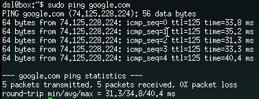
It all works! Not only that, but we have name resolution working properly. That is because we configured the R1 router with the following:
!
ip dhcp pool Finance
   network 192.168.10.0 255.255.255.0
   default-router 192.168.10.10
   dns-server 192.168.81.2
Note that we set the dns-server to point to the IP address of the VMware VMnet8 gateway.
Hope you all enjoyed this article, the Lammle book is a great one to use for CCNA. Happy Computing!
Team-oriented systems mentor with deep knowledge of numerous software methodologies, technologies, languages, and operating systems. Excited about turning emerging technology into working production-ready systems. Focused on moving software teams to a higher level of world-class application development. Specialties:Software analysis and development...Product management through the entire lifecycle...Discrete product integration specialist!
Leave a Reply