NFS via Server 2008 R2 to ESXi: The Book
This article details exactly how to take an arbitrary server, install a *hardened* Windows Server 2008 R2 (W2K8R2) image on it, and then use that W2K8R2 server to deliver NFS to ESXi hosts. We had to do this recently to leverage a bit of local shared storage; read on to see the steps! We put in a lot of detail; the article just kept getting longer and longer – enjoy!
Shared storage is almost a requirement for any respectable vSphere implementation. The underlying ESXi hosts support attaching to block-level storage such as Fibre Channel or iSCSI as well as file-oriented storage such as NFS. In this article we show how a commodity server can provide NFS shared storage to be consumed by ESXi hosts within a vSphere implementation.
The playing field: We used a Dell PE2950 with a security-hardened Windows Server 2008 R2. We have a total of 3 network cards (a dual-port Broadcomm BCM5708C 1GbE NIC) and 2 Intel Pro/1000 PT NICs. Each PE2950 has 5 300GB HDDs running at RAID5 with a hot spare for a total of right around 1.1TB of disk space. While certainly not a lot of storage, in our case every TB helps.
In our case we run in a secure environment where individual hosts must be scanned frequently by Information Assurance (IA). We start by configuring all of the networking components, then install a hardened version of W2K8R2, install and configure the Windows NFS Services role service, and serve to our ESXi hosts.
Basic Server Setup – RAID and OS
This section covers the physical setup for Redundant Array of Integrated Disks (RAID) as well as the operating system setup.
RAID Setup
Normally you setup RAID at the system BIOS prompt; for example, with Dell PowerEdge (PE) servers you would press Ctrl+R during the boot process when prompted. This brings up the disk RAID controller setup screen. In general, setup RAID to maximize disk storage unless you have SATA disks of 1TB or more. This is because RAID5 provides the best disk space ratios of any RAID type compared to failure resiliency:
| RAID Type | Formula | Notes |
| RAID0 | [Number of Disks] x [Size of Smallest Disk] | Fastest but least safe; any disk failure loses the array |
| RAID1 | [Number of Disks] x [Size of Smallest Disk] / 2 | Safest but smallest; very resilient |
| RAID4 | ([Number of Disks] – 1) x [Size of Smallest Disk] | Not generally used (dedicated parity disk is single point of failure). Used within NetApp storage. |
| RAID5 | ([Number of Disks] – 1) x [Size of Smallest Disk] | Fast reads, slow writes; tolerates one disk failure |
| RAID6 | ([Number of Disks] – 2) x [Size of Smallest Disk] | Fast reads, slow writes; tolerates two disk failures |
Additionally, there are other RAID types such as RAID10 (sometimes written “RAID1+0”); we don’t cover these RAID types here other than to note that they are combinations of the base RAID types. RAID10 is a combination of RAID1 (mirrored) and RAID0 (striped); it effectively means that you use RAID0 for a group of disks to stripe data and then mirror the entire RAID0 set to another group of disks. See Wikipedia for more info, however…
Based on the above, to maximize disk space while still being able to survive at least one disk failure, RAID5 is the clear winner. On the downside, RAID5 is slower when writing and can be very unsafe when using larger lower-quality SATA disk drives.
Regarding RAID5 and large SATA disk drives: A great NetApp whitepaper (“NetApp RAID-DP: Dual-Parity RAID 6 Protection Without Compromise”) posits that one can expect a 33.28% failure rate for SATA drives greater than 2TB. Where this becomes most problematic is the issue when using RAID5 – this RAID grouping stripes disk parity across all disks (effectively removing one disk’s worth of space from the array). The issue arises when a disk fails; the RAID5 group can automatically rebuild itself – which is great, unless another disk fails during the rebuild. In that case…data loss! The reason this becomes such a problem with large SATA disks is for two reasons:
- SATA disks generally are lower-quality than SAS or solid state drives (SSDs)
- The rebuild time for a RAID5 array is the inverse of typical write time – much, much slower (
1/nperformance instead ofn/1 where n is the number of disks in the array).
So when rebuilding a RAID5 group on very large, lower-quality SATA drives it simply becomes much more possible that a second disk drive could hiccup or even fail entirely. Thus the 33.28% failure rate. Eck.
For our use case, disk failures are less of an issue. Our physical servers consist of Dell PE2900s with 750GB SATA drives (7.2K/RPM) and Dell PE2950s running 300GB SAS drives (15K/RPM). Thus we are less concerned about the perils of using RAID5 for disk management; as long as we have some spare disks in the datacenter *and* we can configure the RAID5 arrays to use a “hot spare” (separate disk ready to be integrated as soon as a disk failure is detected) we should be acceptable.
Operating System (OS) Setup
In our use case, servers were built from hardened “Army Golden Master” editions of Windows Server 2008 R2 with all service packs and patches applied. Additionally, these servers were joined to the local Active Directory (AD) and applied to the various AD group policy objects (GPOs). For example, one such GPO is named “WSUS Protected Servers” and provides the policy we use to ensure that Windows Server Update Services (WSUS) security patches do not result in unplanned automatic reboots.
Switch Setup
To get full redundancy, a separate switch / network fabric should be used to differentiate management (e.g. remote access to server via Remote Desktop) from storage (access from the ESXi hosts to the NFS server running on the Windows Server 2008 R2 box). In this use case, we have two switches involved: a top-of-rack switch for the physical server (used for Management traffic – VLAN 210) and a separate storage switch (used for Storage traffic – VLAN 240).
Management Switch Setup
This is straightforward; simply enable the port and set the Port-based VLAN ID (PVID) tag to “210” for the selected management NIC. This ensures that all network traffic outbound from the server over the switch will have a proper Virtual LAN (VLAN) tag applied to it where “210” is the VLAN tag that identifies management network traffic.
The following screen shows how, for a NetGear GS748TS programmable switch, a PVID can be set for a given connected port (the connection from the assigned NIC on the physical server to the RJ-45 port on the switch itself):
In the above shot, port 2 (1/g2 on the physical switch) has had a PVID of 210 applied to it. Again, this ensures that all outbound traffic received from the connected host will have a VLAN tag of “210” applied to it.
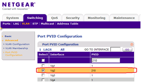
For inbound network traffic, the switch must enforce that only traffic with the “210” VLAN tag is allowed to be sent to the connected server. (This is generally known as “VLAN trunking” within the networking world.) Within the NetGear switch, the following shot shows how a VLAN tag is “trunked” to accept inbound traffic with VLAN tag 210:
Now that the management networking is setup, it is time to setup storage networking on the switch.
Storage Switch Setup
In our use case, the separate Storage switch is also aNetGear GS748TS 48-port programmable device:
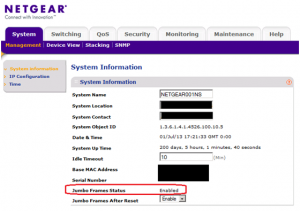
- Ensure jumbo frames enabled on the switch. By default IP frames are 518 bytes which results in a large number of “fragments” as large data packets are broken up into smaller frames. This fragmentation results in extra network traffic and – generally – in lower network file I/O. The use of jumbo frames can alleviate this problem; jumbo frames enable up to 9000 bytes to sent per frame. For large disk I/O transfers, this results in fewer overall network frames and – again, generally – in improved performance.
Technical details: NFS uses up to 8192 bytes for each read / write request, so jumbo frames can be quite useful. (Generally, between 5% and 15% performance boost – see this blog post for more details). Jumbo frames must be enabled at each device used in the storage network; how a switch has jumbo frames configured for it changes by switch manufacturer. The below screenshot shows how jumbo frames were enabled for our example NetGear switches:
-
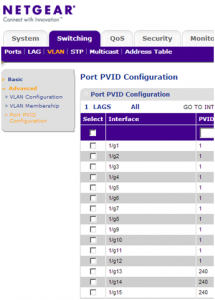
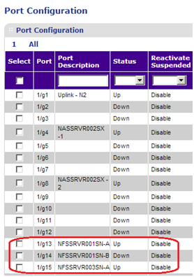
Enable the switch port (and update your local documentation!). The following shot shows ports 13, 14, and 15 named based on the connected station and enabled. (Port 14 is not enabled because we are not concentrating on NIC teaming for this use case):

-
Setup the Port PVID Configuration to specify the selected port with a VLAN tag of 240. This attaches VLAN tag to egress traffic. In the shot below ports 13, 14, and 15 are configured:
-
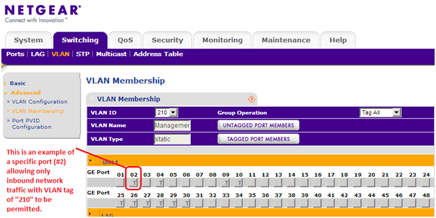
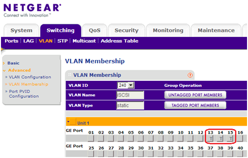
Setup the VLAN membership; this permits tagged ingress traffic to be delivered to that port. The following shot shows ports 13, 14, and 15 attached to VLAN 240 (the primary Storage VLAN):


Except for the jumbo frames (which are not required on the Management network), this setup is basically the same as for the Management VLAN from the previous section.
Network Interface Card Setup
Each Windows Server 2008 R2 server has at least one Network Interface Card (NIC) connected to each of the Management and Storage networks. Of course, it is best to have redundancy here as at every layer in the infrastructure: 2 switches to pass traffic, 2 NICs on each connected server “teamed” to each switch, redundant power supplies, redundant disk controllers – you name it, if you do not have redundancy then you are at risk. For this use case, however, we concentrate on the specific network settings.
NIC Setup and Firmware
For this use case, each server has dual on-board Broadcom BCM5708C 1GbE cards as well as dual standalone Intel NICs. The layout is:
- Intel NIC – Used for Management (VLAN 210)
- Broadcom BCM5708C – Could be configured as a load-balanced Team to present to ESXi hosts (VLAN 240). This would permit up to 2GbE NFS storage throughput from the Windows Server 2008 R2 host. Setting up a NIC team (either for failover or for load-balancing) is beyond the scope of this document.
Important point – always check for NIC firmware updates: In our case, the latest Dell PE2950 Broadcom firmware 7.4.8 needed to be downloaded and installed on each server. Then used the Dell PE2950 Broadcom NetXtreme II Base Driver v14.2.2 (A03). Otherwise, the Broadcom NICs are not recognized by Server 2008 R2 after applying all Windows Updates.
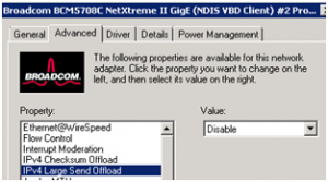
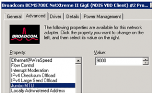
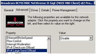
For each NIC, set the following advanced options:
-
IPv4 Large Send Offload – Disable if you find instructions to do so (for example, the Broadcom BCM5708C NIC has had problems with Server 2008 as documented in blog entries such as this Dell support forum entry for the PE2950.
-
Jumbo MTU – 9000. Always set this for an NFS server!

Continue to the next section.
IP Addressing for Management and Storage Networks
Up to this point we have addressed the switch programming to segment Management traffic from Storage traffic (via VLAN 210 for Management, 240 for Storage). However, we have not discussed what IP addresses each function should have.
For this use case, in addition to the VLAN segmentation we have two different IP subnets:
- Management: 172.24.1.0/24; GW 172.24.1.1; DNS 172.24.4.2,172.24.4.3
- Storage: 172.28.4.0/24 [no gateway] [no DNS]
What the above means is that each NIC within the Windows Server 2008 R2 box will have a network address assigned to it based on the IP subnets. For the Management network, we have a single “255.255.255.0” subnet (otherwise known as “/24” because it is 24 bits of masking) that allows up to 254 distinct IPs (two IP addresses are reserved in every subnet). The same goes for the Storage network; it is also a “/24” subnet allowing up to 254 distinct IPs. The actual IP addresses will be assigned by the network administrator, but the key point here is that – just as with the VLAN tags – the Management and Storage networks have different values.
In the screenshot below, we show that the Storage adapter (“dvPgStorage”) has IP address 172.28.4.21 while the Management adapter has IP address 172.24.1.21. Moreover, we show that the server can properly ping one of the ESXi hosts attached to the Storage network (this is the ping 172.28.4.95 command).
Please note that – for the Storage (“dvPgStorage”) network – there is neither gateway nor is there any DNS information. That is because the Storage network is completely internal; only the Management network requires network ingress / egress:

Note in the above that the ping command uses flags to send a jumbo frame to the ESXi host (8972 bytes by using “-f -l 8972“). This is actually the maximum size of a jumbo frame’s data – the 28 “missing” bytes are the overhead from the IP header itself; this header is automatically prepended to every data frame sent across the network.
NFS Setup the Windows Server 2008 R2
Follow these steps:
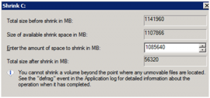
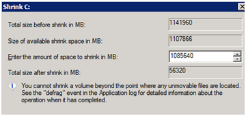
- If you created a single RAID5 group on your Windows server, then shrink the OS partition to ~55GB as shown below. This ensures that you do not mix your shared NFS storage shares with your raw OS code:
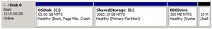
Next, create a separate partition for the shared storage with max space available as shown:
-
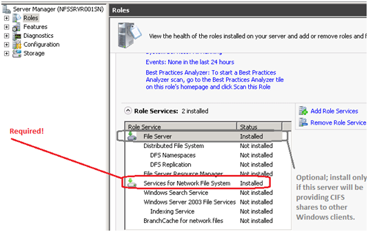
Install Services for Network File System as shown below. Note that File Services are not required for NFS; only install File Services if this same Windows Server 2008 R2 box will be used to serve Common Internet File System (CIFS) “Windows” shares directly to non-ESXi consumers such as other Windows clients:

-
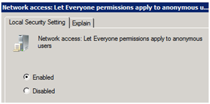
Enable anonymous access via “
Network access: Let Everyone permissions apply to anonymous users” policy. This is required for the ESXi hosts to be able to access the NFS shares from the Windows server: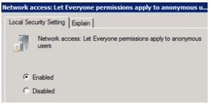
NOTE: This can be set at AD GPO level as well as at local level.
-
Setup NFS version 3 support and ensure TCP is used for the protocol by executing these commands within an elevated command prompt:
nfsadmin server %computername% config enablev3=yes
nfsadmin server %computername% config mountprotocol=tcp
- Reboot the Windows server.
-
Log back in to the Windows server and – from an elevated command prompt – setup the client groups:
nfsadmin server creategroup ESXiHosts
nfsadmin server addmembers ESXiHosts 172.28.4.90,172.28.4.91,[...]
Just add more host IPs to enable more ESXi hosts to hit the NFS share – which we have not yet created 🙂
-
Create the NFS share as below (use elevated command prompt):
nfsshare EsxiStore=E:\EsxiStore -o rw=ESXiHosts -o root=ESXiHosts -o anon=yes
After creating the share, you must grant “Full control” to the Everyone group for the NTFS permissions (the above command simply sets the NFS access permissions, which are separate from NTFS permissions):
icacls E:\EsxiStore /grant Everyone:F
The share is now ready to be consumed by ESXi.
ESXi Consumers
In the previous section the NFS service was configured and the share created. Consuming the share within ESXi host is straightforward:
-
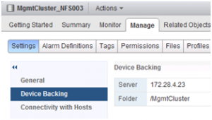
Open vCenter Server and create a new NFS datastore. This is as simple as connecting to the Windows Server 2008 R2 from the vSphere Web Client (or vSphere Client). The following shot shows an NFS datastore from one of our legacy Windows Server 2008 R2 served as part of a vSphere storage cluster:
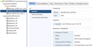
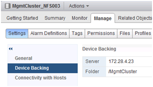
This next screen shows the NFS server connection (“Device Backing”) from the same screen (IP settings):
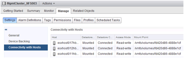
And, finally, we show how three of our ESXi hosts are consuming this NFS storage (once again, from the same screens for the NFS datastore):

-
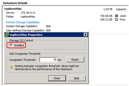
Important point on the above: the first screenshot of the storage cluster shows that Storage I/O Control (SIOC) is enabled for the datastore. This is critical: ESXi will have problems using the Windows Server 2008 R2 box as an NFS server unless SIOC is enabled; the following shot shows the vSphere Client with SIOC enabled to a datastore:
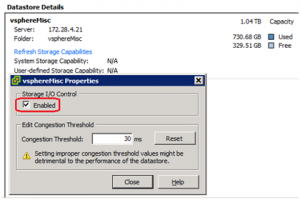
Usage of SIOC requires Enterprise Plus license; alternatively, you can set
QFullSampleSize/QFullThresholdadvanced ESXi options as described in the VMware KB 1008113 article.

Final thoughts: The storage can now be used within ESXi like any other NFS datastore. Even with SIOC, do not be too aggressive storing VMDKs or cloning machines; Server 2008 R2 is not an officially-supported NFS provider for vSphere so you are on your own if things go wrong.
Team-oriented systems mentor with deep knowledge of numerous software methodologies, technologies, languages, and operating systems. Excited about turning emerging technology into working production-ready systems. Focused on moving software teams to a higher level of world-class application development. Specialties:Software analysis and development...Product management through the entire lifecycle...Discrete product integration specialist!
thanks for this awesome tutorial 🙂 .
Thanks for the write-up. -a USAF SysAdmin